-40%
Palomar Skipper 300 Linear Amplifier Refurb Kit HVCapRect Transistor Model 1&2
$ 13.17
- Description
- Size Guide
Description
READ FIRST BEFORE CLICKING BUY IT NOW !This is
NOT AN OEM KIT.
The parts in this kit will get your amplifier working because these electronic parts have the same function & electrical characteristics of the original equipment parts. All Capacitors are radial not Axial. Of course. Usable tubes. Functioning Relays. Some parts may be of a higher current or voltage rating than original. They will work fine. The transistors may not be the same part number. but they will work if installed correctly. E.B.C. Emitter Base Collector.
You have to have
TOOLS
such as : 30 to 60 watt Iron or variable larger
soldering gun. Solder paste , at least one surgical tweezers ; needle nose pliers & Cheap Analog Multi-meter. Optional but good to have. Transistor checker/Capacitor tester.
A basic understanding of BJT transistors like emitter, base , collector LOCATION. The legs of the PNP or NPN transistors in the kit. How Diodes function. Signal & rectifier diodes. Anode - cathode. Capacitors - +.Relays.
You can teach yourself quickly these basics.
DO NOT BUY THIS KIT IF YOU
THINK IT IS "PLUG & PLAY" & DO NOT BUY IT IF YOU THINK IT IS SOMETHING
Else OTHER than a Collection of PARTS to be Installed BY YOU.
Two versions of Skipper 300 were manufactured. Early has metal toggle switches. It is "Hard Wired". No circuit boards. Later version has flimsy plastic toggle switches & circuit boards plus different relays. Schematic is available for Generation 1 online CB tricks. Unfortunately not for Generation 2 or LDO Skipper Clone. LDO Skipper Clone is a bit different from generation 1&2 Palomar.
Generation 1 Skipper Hard Wired. Will be sent automatically UNLESS YOU SPECIFY
otherwise.
This listing is also for generation 2 & LDO Skipper Clone. 20 No insertion charge adds only per month . Soooo One Listing for all versions of Skipper ! Below is a second parts list description for Generation 2 & LDO Clone. I have an LDO. It's design is a bit better
than the original Palomar 1&2. LDO = Long Distance Operator.
Generation Two Skipper 300 uses Two circuit boards. I do not have a Schematic. However; I own a generation two. 1st generation uses robust metal toggle switches. 2nd flimsy plastic toggles.
However; Generation 2 uses better relays + Military Spec 3 Amp diodes and an improved circuit. Recently my Generation Two had issues. Lot of noise in my receiver
whenever I cranked up the Skipper. HV caps had been replaced. Also 1000uf cap.
But not the others ! Not bad 36+ years. Soo. Gues what. Generation 2 requires a slightly different kit.2X 22uf & 47uf caps. LDO Clone has a Superior B+ relay than 1&2.
Now. Please read. These are not OEM replacements. Modern Caps are quite small compared to the originals made back in the day LOL.
Negative feedback "Sent wrong Parts"? Just can't please everyone. Sent the right ones.
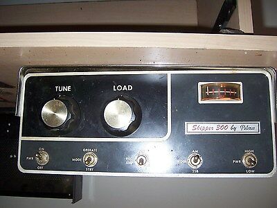
The best Sweep tube Amp in this power rating ever made. Dating from the seventies and
despite large numbers were not made-they are plentiful and in demand.
Originally a companion to the AM/SSB Palomar in a similar chassis.
Robust transformers, beautiful chassis. Compact design.
This unit is not like the 300M model which required having a fire extinguisher handy.
This Kit contains 3 NEW x 2905 transistors for the keyup and pre-amp circuit.
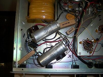
2 X NEW Modern High Voltage 105"C, Low Leakage low resistance 450v 120uf Capacitors.
From my experience re-furbishing and re-tubeing these Palomars 120uf pair is better
than
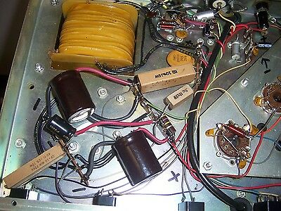
100uf 80uf or the 60uf originals. As you can see from the photos. Installing a
modern
low leakage low esr HV electrolytic is a snap. Equivalent quality or inferior axial
lead
capacitors or NOS caps are substantially more expensive than this kit.
New Old Stock HV Capacitors have an issue that is overlooked in the heat of the
moment of wanting to fix a HV supply. Age. Whether being used or not sitting on a
shelf Capacitors slowly degrade with age. There is a specific lenghy process called
reforming electrolytic capacitors. Who's got the time for that ?
The added benefit of this kit
is upgrading the rectifier diodes. Yes. The silicon diodes
do wear. They can open or short out. Just a few minutes. Fresh set installed. Keep an
eye on the "Band end" cathode. Replace one at a time. Mark the band end on the
chassis. The original is 1 AMP. The upgrade is 3 Amps & a larger diameter.
Extra key-up/receive pre-amp transistors or upgrade and or replacement.
low
voltage caps makes this kit cost effective and desirable.
Premium low esr low leakage 1 x 1000uf upgrade for keyup circuit ,pre-amp and
bias.
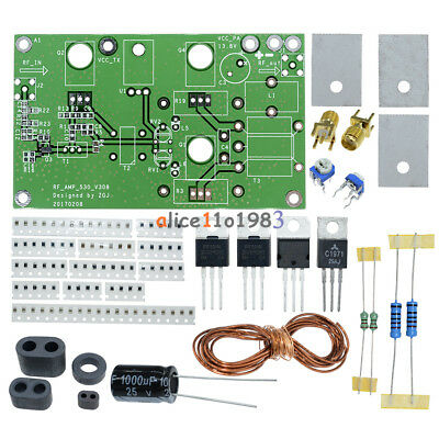
GENERATION 1 Parts List
2 x 10uf 25v electrolytes
4 x upgrade 3 amp rectifier diodes.
1 x Low voltage 1 amp Rectifier Diode
3 X low voltage Signal Diodes......................In case the signal diodes wired on the + plus
& negative terminals of the three RELAYS have shorted or opened.
3 x 2905 transistors. 1 for receive pre-amp 1 for key-up circuit 1 extra !
2 X 120uf 450v Low leakage, Low ESR modern FRESH Capacitors.
1x 1000uf 35v Electrolytic " " " " "
______________________________________________________________________
GENERATION 2 Palomar Skipper & LDO Clone
1 x 47uf 25v
2 x 22uf 25v electrolytic
2 x Small signal Diodes
4 x upgrade 3 amp rectifier diodes.
1 x low voltage rectifier
3 x 2905 transistors. 1 for receive pre-amp 1 for key-up circuit 1 extra !
2 X 120uf 450v Low leakage, Low ESR modern FRESH Capacitors.
1 x 1000uf 25v Electrolytic " " " " "
These Voltages can be Lethal. Unplug amplifier. Short the positive terminals of the caps
to the chassis.
Carefully remove the tubes or leave the chrome part of the amp on the chassis. Then
carefully flipping it overo the top rests flat exposing the work area .
The tubes without the top extend past the main chassis and are very fragile as well as
expensive.
Happy DX-ing Best 73s..........High Voltage...Make sure your Solder connections are
nice and shiny. 40 watt minimu solder iron. Bigger is better in this type of hard wired
circuit. Bigger Iron that is.
If your unit was working with the original HV caps. Or 60 to 80uf caps. You will notice
a slight increase in PEP output. If they are 100uf-120uf and old. You will see a slight
increase. Your HV transformer will not work as hard with new large capacity Caps.
Run a tad cooler under most keyup conditions. Of course it is not a Broacast Linnear Amp !
Check...Check and recheck your work. + - etc. wired to the proper posts.
I work from 9-5. I try my best to get to the Post Office to ship the item out.
Please Remember to leave me positive feedback. Thanks
Directions;.............Unplug-Precaution-Short + To Chassis of old HV-Electrolytics. Even though balancing resistor and bleed resistors are in this well designed circuit.
1) Mark all positive and negative Terminals.
2) lift up unsolder one leg at a time of old caps
3)Leave the others in place. I start with the red positive terminal first.
4) Solder your Color coded Insulated wires unto your new HV
capacitors. Red = + Black negative. I use steel braided wire scraps salvaged from microwaves, outdoor ballasts etc.
Reason is- It holds the new parts in place and I do not have to use a Hot Glue Gun to paste the caps to the chassis.
Any stranded wire will do. But observe the Color code.
5) Install and remove one at a time. Use longer than you need.
Trim and tin once you eyed the distance between posts. Use the eyes of the posts to slip your wire ends.
6) 25v 10uf install and removal of old ones. Mark the + & -.
7) Use the empty needle hole on the posts. The new caps are tiny !
8) One leg at a time observing Polarity. Remember to take a scrap red piece of insulation and slip it over the + leg of new
cap.
9) Diodes- One at a time. Observe the BAND end - cathode
of the old and new rectifier diodes. One leg at a time. Unsolder
then solder new end. Again at other end. Using you needle nose. Bend fold hook leads through posts.
Your Solder joints should be shiny and physicaly strong.
A variable with a minimum of 60 watts iron. HF stores sell
a good cheap Iron and kit. With %20 off coupon a bargain and useful tool.
I have large Weller guns that are not made anymore.
The small signal dides you see rarely go bad unless they were accidentally shorted.
2N2905 Emitter Base & collector. Take a photo first of the chassis ?
Orient the tab correctly. Mark the chassis where this tab points.
Unsolder first two legs or cut with small wire cutter. Solder your pre-tinned new legs.
Then the last one. Avoid excessive heat. Use a surgical tweezer
when installing to hold the new part. It also draws the excessive heat from the new 2N2905.
When you add the legs of wire to the New HV cap. Wrap your
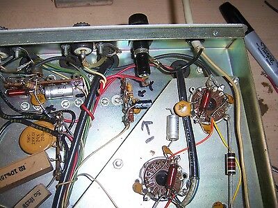
wire end around the post. Then bend it. Then solder. I lost most of the step by step pictures. But. The ones I retook ought to give you an idea how to proceed.
Copy Paste & Print this out !
Good Luck !
